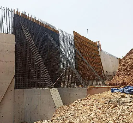

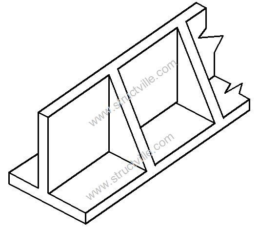
Retaining walls are structures used for supporting earth materials at different levels. There are different types of retaining walls such as cantilever retaining walls, gravity retaining walls, counterfort retaining walls, buttressed retaining walls, etc. Counterfort retaining walls have similarities with cantilever retaining walls, with the difference of having triangular or rectangular web panels spaced at regular intervals at the back of the retaining wall.
These web panels are called counterforts, and they serve the purpose of tying the base slab and the wall (stem) together. By so doing, they reduce the internal stresses induced in the structure and increase the weight of the structure for stability. The main characteristic of a counterfort retaining wall is the inclusion of the counterforts.
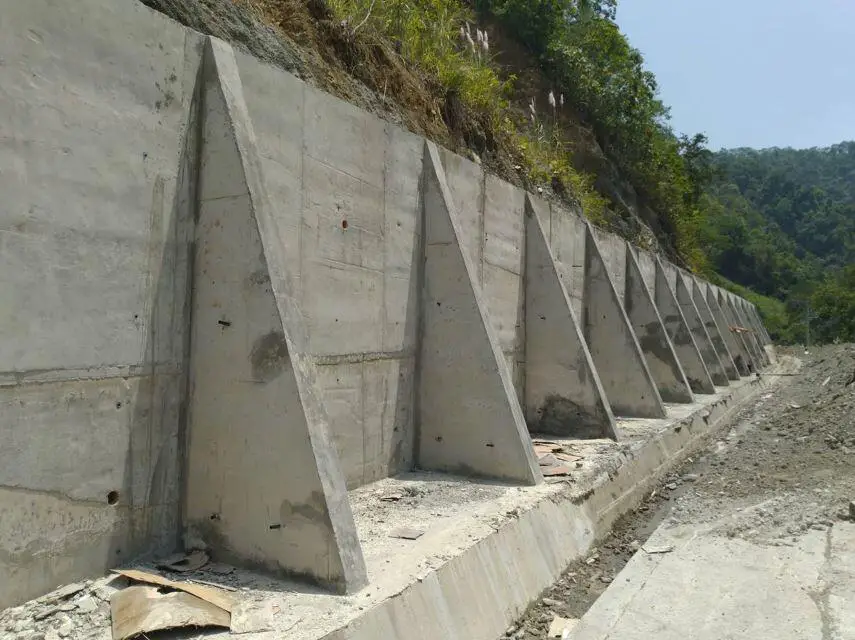
These counterforts are positioned at regular intervals along the length of the wall, extending from the base to the top. They act as braces or buttresses, helping to distribute the lateral forces exerted by the retained soil.
The counterforts are connected to the main wall, known as the stem, by horizontal slabs or beams called tie beams. These tie beams create a robust structure, distributing the forces evenly and increasing the overall stability of the wall. The toe of the wall is typically thicker and wider than the stem, providing additional resistance against overturning and sliding.
The design of a counterfort retaining wall takes into account factors such as soil properties, anticipated loads, and water pressure. It must be designed to withstand the lateral pressure exerted by the retained soil and any potential surcharges, such as additional loads from adjacent structures or traffic.
One advantage of counterfort retaining walls is their ability to span longer heights compared to other types of retaining walls. The presence of counterforts and tie beams enhances the structural integrity, allowing for the construction of taller walls. This makes them suitable for applications where a high retaining wall is required, such as highway embankments, bridge abutments, and building foundations.
Another advantage is the ease of construction. Counterfort retaining walls can be built using precast concrete elements or cast-in-place methods, depending on the project requirements. The use of precast elements can expedite the construction process and reduce costs.
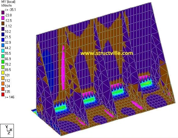
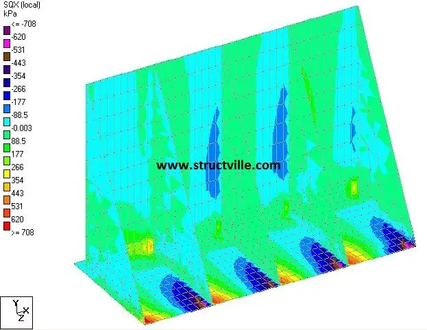
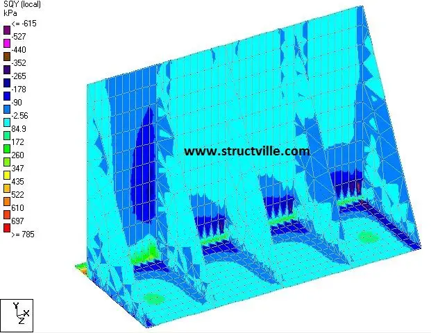
Counterfort retaining walls can be easily modelled on Staad Pro software, and loaded to obtain the internal forces and deformations due to the retained earth. We are going to demonstrate that using the video below.
The data on the retaining wall is shown below;

Design Data
Height of wall from base = 7 m c/c
Length of base = 4.5m
Projection of toe = 0.8 m c/c
Projection of heel = 3.7 m c/c
Thickness of stem wall = 0.3 m
Thickness of base = 0.5 m
Thickness of counterfort = 0.3 m
Spacing of counterfort = 2.5 m c/c
Unit weight of concrete = 25 kN/m 3
Unit weight of retained earth = 19 kN/m 3
Angle of internal friction φ = 30°
Surcharge pressure on retaining wall = 10 kN/m 2
Modulus of subgrade reaction of supporting soil = 50000 kN/m 2 /m
We are going to neglect the effect of passive earth pressure on the retaining wall.

Coefficient of active earth pressure Ka = (1 – sinφ)/(1 + sinφ) = 0.333
Earth pressure at the back of the wall (triangularly distributed) = 0.333 x 19 kN/m 3 x 7m = 44.289 kN/m 2
Surcharge pressure at the back of the retaining wall = 0.333 x 10 = 3.33 kN/m 2
Earth pressure on the base (heel) = (7m x 19 kN/m 3 ) = 133 kN/m 2
Surcharge pressure on the base (heel) = 10 kN/m 2
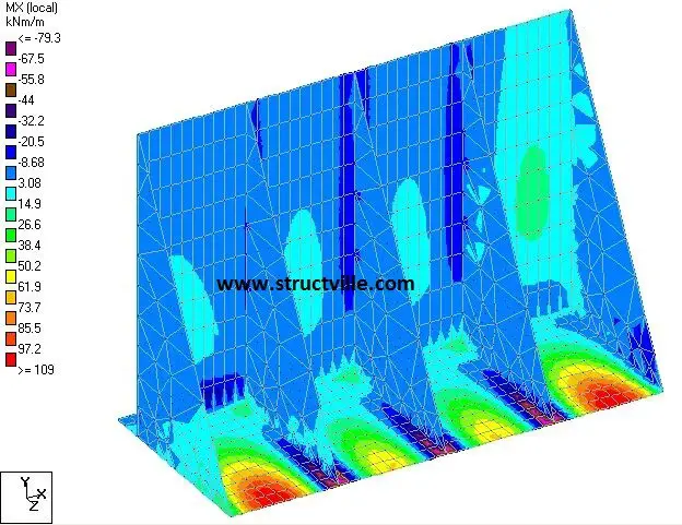
Watch the video for the analysis of counterfort retaining walls on Staad Pro below;
